8.1. Field Encoding and Calculation Techniques
This chapter describes in detail how key fields (I-CNT, HIST, U-ADDR/F-ADDR and TSTAMP) are calculated and encoded.
8.1.1. Address Compression
Address transmissions is compliant with the IEEE-5001 Nexus Standard (most significant bit 0-s skipped) with optional extension allowing to skip identical most significant bits. See Virtual Addresses Optimization chapter below for clarifications.
Rules when generating addresses:
-
Only execution addresses (as seen by the hart) are reported. When virtual memory system is enabled these are virtual addresses.
-
The F-ADDR field is the full address associated with the trace event, provides a starting point for reconstructing relative addresses.
-
The U-ADDR field is a compressed address that is relative to the previous trace message with an address field. It is generated by XORing the address with the previous message.
-
To decode the full address from the relative address (U-ADDR) can be XORed with the previously decoded full address.
-
-
Address fields are sent beginning with bit 1 since all execution addresses are on a 2-byte boundaries (the least significant bit is always 0 and never sent).
Address XOR Calculation Examples
==============================================================================================
| Address   | U-ADDR XOR calculations       | F-ADDR/U-ADDR field sent             | New REF |
|           |                               |                                      | Address |
==============================================================================================
|0x3FC04    |                               | F-ADDR=1_1111_1110_0000_0010=0x1FE02 | 0x3FC04 |
----------------------------------------------------------------------------------------------
|0x3F368    | REF =0011_1111_1100_0000_0100 |                                      |         |
|           | addr=0011_1111_0011_0110_1000 |                                      |         |
|           | XOR =0000_0000_1111_0110_1100 | U-ADDR=111_1011_0110=0x7B6           | 0x3F368 |
----------------------------------------------------------------------------------------------
|0x3E100    | REF =0011_1111_0011_0110_1000 |                                      |         |
|           | addr=0011_1110_0001_0000_0000 |                                      |         |
|           | XOR =0000_0001_0010_0110_1000 | U-ADDR=1001_0011_0100=0x934          | 0x3E100 |
==============================================================================================
8.1.2. HIST Field Generation
When operating in HTM mode, the encoder does not generate messages for conditional branches. Instead, it maintains a HIST register or accumulator to record the outcomes of these branches, whether taken or not-taken. Each conditional branch contributes a single bit to the HIST register, as follows:
-
A bit with a value of 1 is appended at the least significant position for a taken conditional branch.
-
A bit with a value of 0 is appended at the least significant position for a not-taken conditional branch.
The HIST register may be implemented as a left-shift register. Initially, when the HIST register is empty, bit 0 of the register is set to 1, with all other bits set to 0. Subsequent conditional branches cause the register to shift left, recording each taken or not-taken outcome in bit 0.
Examples:
Binary(MSB-LSB):   101=0x5  (two direct conditional branches, not-taken and taken)
Binary(MSB-LSB):  1111=0xF  (three direct conditional branches, all three taken)
Binary(MSB-LSB): 10000=0x10 (four direct conditional branches, all four not-taken)
Binary(MSB-LSB):     1=0x1  (no direct conditional branches at all)
After transmission of the HIST field, the register is reset to its initial, empty state.
Decoders must initiate the interpretation of the HIST field starting from the second most significant bit. The most significant bit, designated as the stop-bit, is invariably set to 1. This second most significant bit—immediately following the stop-bit—encodes the outcome of the first conditional branch captured in the HIST register. Conversely, the least significant bit represents the outcome of the last conditional branch prior to the transmission of the HIST register.
8.1.2.1. HIST Field Full
The transition of the most significant bit in the HIST register from 0 to 1 indicates the register is full. At this point, the entire register, including the most significant bit — which serves as the stop-bit — is transmitted using a ResourceFull message with the RCODE field set to either 1 or 2.
When a HIST register is full and its value is the same as that of the HIST field transmitted in previous ResourceFull message, then the encoder may increment an internal HREPEAT counter (history repeat counter) instead of generating a ResourceFull message if the Repeated History Optimization is enabled. See Repeated History Optimization chapter for further details.
| Trace decoders do not have to be aware about the actual size of the HIST field implemented by the encoder, however, to allow efficient implementation of trace encoders (and allowing HIST pattern detection) this N-Trace specification limits HIST field size to max 32-bits. Longer HIST fields would not provide much of a gain and would make repeated HIST field detection more costly (in terms of hardware resources). |
8.1.3. I-CNT Details
The I-CNT field, present in most messages, transmits the value of the I-CNT counter, which counts the number of halfwords used to encode retired instructions.
The I-CNT counter in the trace encoder is reset to 0, in accordance with the IEEE-5001 Nexus Standard, under one of the following two conditions:
-
When tracing starts or is restarted for any reason.
-
After the I-CNT counter value has been transmitted in a message.
Every retired instruction MUST increment I-CNT counter by 1 (for 16-bit instruction) or by 2 (for 32-bit instruction). Specifically:
-
If an instruction is explicitly changing the PC (as jump or return), that instruction itself MUST update the I-CNT.
-
Instructions that either raise exceptions or are interrupted prior to retirement do not increment the I-CNT counter.
| In case of longer instructions (48-bit, 64-bit, …) (future ISA standards or custom) I-CNT may increment by 3 or more. |
When I-CNT counter is full (reaches its maximum value or overflow bit is set) it can be reported in one of two ways:
-
By using a ResourceFull message with RCODE=0. This method is applicable to both BTM and HTM.
-
Optionally, by using a synchronizing message with SYNC=4 (Sequential Instruction Counter). It may be only used in BTM mode.
| Overflow bit allows efficient handling of cases, when single ingress port cycle reports bigger I-CNT (several instructions retired). Reporting maximum value (exactly) is not required and smaller or bigger value may be reported instead. |
8.1.3.1. Example of I-CNT Handling in BTM mode
As an illustration, let’s consider the following piece of pseudo-code (specific operations are abstracted as "…" as they do not matter for this example):
0x100:  c.add ...       ; 16-bit instruction
0x102:  b... 0x200      ; 32-bit instruction (direct conditional branch)
0x106:  add ...         ; 32-bit instruction
0x10A:  b... 0x300      ; 32-bit instruction (direct conditional branch)
0x10E:  c.add ...       ; 16-bit instruction
0x110:  add ...         ; 32-bit instruction
0x114:  c.ebreak        ; 16-bit breakpoint (to stop the code)
...
0x200:  c.add ...       ; 16-bit instruction
0x202:  c.ebreak        ; 16-bit breakpoint (to stop the code)
...
0x300:  add ...         ; 32-bit instruction
0x304:  c.ebreak        ; 16-bit breakpoint (to stop the code)
| In the description below a range specified as <0x100..0x105> means that addresses 0x100 and 0x105 are both included in the address range. |
Let’s assume we start a trace from address 0x100. The ProgTraceSync message with I-CNT=0 and F-ADDR=0x80 (encoding an address 0x100) should be generated.
Let’s analyze a collected trace of above program (in BTM mode) executed three times (each time with different flow).
-
First direct conditional branch at address 0x102 is taken.
-
A DirectBranch message with I-CNT=3 should be generated. It means, that a code block from <0x100..0x105> (as 6=2*3) was executed and a direct conditional branch at the end of this block was taken. Decoder will know PC=0x200 from an opcode of the direct conditional branch at an address 0x102.
-
Next message should be ProgTraceCorrelation with I-CNT=1 describing range <0x200..0x201> till C.EBREAK instruction.
-
-
First direct conditional branch at address 0x102 is not taken and second direct conditional branch at address 0x10A is taken.
-
A DirectBranch message with I-CNT=7 should be generated. It means, that a code block from <0x100..0x10D> (as 0xE=2*7) was executed and a direct conditional branch at the end of this block was taken. Decoder will know PC=0x300 from an opcode of the direct conditional branch at an address 0x10A.
-
Next message should be ProgTraceCorrelation with I-CNT=2 describing a range <0x300..0x303> till C.EBREAK instruction.
-
-
Both direct conditional branches (at 0x102 and 0x10A) are not taken.
-
In this case only ProgTraceCorrelation with I-CNT=10 should be generated. It is describing a range <0x100..0x113> (as 0x14=10*2) till C.EBREAK instructions.
-
| Decoder must analyze every instruction in each code block being processed to know its size. It cannot skip to the end of the block by calculating PC+I-CNT*2 as it is UNKNOWN what is the size of the last instruction retired in that block. It may be (compressed) 16-bit or 32-bit (not-compressed) direct conditional branch. Without knowing an instruction size, the offset encoded in that direct conditional branch cannot be determined and the next PC (after a branch) cannot be calculated. |
Above we analyzed some I-CNT values. Let’s consider other I-CNT values.
-
I-CNT=1 is a correct value.
-
The only valid reason to generate a message with I-CNT=1 would be an exception (or interrupt) at an instruction at address 0x102.
-
In this case an encoder should generate an IndirectBranch or IndirectBranchSync message with I-CNT=1, B-TYPE=1 (exception) and U-ADDR/F-ADDR field encoding an address of an exception/interrupt handler.
-
-
I-CNT=5 is also correct.
-
It means that exception/interrupt happened before an instruction at an address 0x10A (after instruction at 0x106).
-
-
I-CNT=0 is also possible.
-
It should be generated when an interrupt was pending before we started the code (and trace) and instruction at address 0x100 was not executed/retired.
-
Another reason for I-CNT=0 may be a case, where instruction at address 0x100 will generate page fault or is illegal.
-
|
8.1.3.2. Example of I-CNT Handling in HTM mode
When the encoder is operating in HTM mode, I-CNT should be incremented at every retired instruction the same way as for BTM mode. However direct conditional branches (from code piece above …) will NOT generate any trace messages, but each of them will add a bit to the HIST field.
Example code (used to illustrate BTM trace) may generate messages with the following fields (for all three runs):
-
First direct conditional branch at address 0x102 is taken.
-
I-CNT=4, HIST=0x3 (0b1_1). Most significant bit=1 is stop bit, bit pattern '1' means that first direct conditional branch was taken. Encoder should continue till an address 0x200 (as the first direct conditional branch encountered was reported as taken) as I-CNT=3 describes a <0x100..0x105> range. Remaining I-CNT=1 describes a <0x200..0x201> range.
-
-
First direct conditional branch at address 0x102 is not taken and second direct conditional branch at address 0x10A is taken.
-
I-CNT=9, HIST=0x5 (0b1_01). Most significant bit=1 is stop bit, bit pattern '01' means that first direct conditional branch was not taken and second direct conditional branch was taken. Encoder should continue till an address 0x300 (as the second direct conditional branch encountered was reported as taken) as I-CNT=7 describes a <0x100..0x10D> range. Remaining I-CNT=2 describes a <0x300..0x303> range.
-
-
Both direct conditional branches (at 0x102 and 0x10A) are not taken.
-
I-CNT=10, HIST-0x4 (0b1_00). Most significant bit=1 is stop bit, bit pattern '00' means that two direct conditional branches were not taken. Encoder should continue till an address 0x114 as I-CNT=10 describes a code in a <0x100..0x113> range.
-
8.1.3.3. Examples of I-CNT Field Full Generation
Let’s consider the following example code:
0x100:  c.add ...       ; 16-bit instruction
0x102:  b... 0x200      ; 32-bit instruction (direct conditional branch)
0x106:  add ...         ; 32-bit instruction
0x10A:  add ...         ; 32-bit instruction
0x10E:  add ...         ; 32-bit instruction
0x112:  add ...         ; 32-bit instruction
0x116:  add ...         ; 32-bit instruction
0x11A:  c.add ...       ; 16-bit instruction
0x11C:  c.ebreak        ; 16-bit breakpoint (to stop the code)
and let’s assume (for simplicity) that the I-CNT counter is 4-bit wide (most significant bit being an overflow flag) and that direct conditional branch at an address 0x102 is not taken (so code will run from address 0x100 till breakpoint at address 0x11C).
Trace with Resource Full message (HTM mode shown):
-
ProgTraceSync (start of trace)
-
SYNC=3 (Exit from Debug Mode), I-CNT=0 (nothing executed as we are starting)
-
F-ADDR=0x80 (encoding starting address 0x100)
-
-
ResourceFull (I-CNT overflown to 9 at an address 0x112)
-
RCODE=0 (I-CNT counter is full), RDATA[0]=9 (I-CNT value overflown value)
-
-
ProgTraceCorrelation (describes entire <0x100..0x11C> range)
-
EVCODE=0 (Entry into Debug Mode), CDF=1 (I-CNT and HIST fields follow)
-
I-CNT=5 (see note below), HIST=0x2 (one not-taken direct conditional branch)
-
Trace with SYNC=Sequential Instruction Counter (BTM mode only):
-
ProgTraceSync (start of trace)
-
SYNC=3 (Exit from Debug Mode), I-CNT=0 (nothing executed as we are starting)
-
F-ADDR=0x80 (encoding starting address 0x100)
-
-
ProgTraceSync (I-CNT overflown to 9 at an address 0x112)
-
SYNC=4 (Sequential Instruction Counter), I-CNT=9 (see note below)
-
F-ADDR=0x89 (encoding address 0x112)
-
-
ProgTraceCorrelation (describes <0x112..0x11C> range)
-
EVCODE=0 (Entry into Debug Mode), CDF=0 (only I-CNT field follows)
-
I-CNT=5 (see note below)
-
Notes (for both trace options)
-
Overflown I-CNT=9 (or RDATA[0]=9) field describes <0x100..0x112> range (18 bytes long).
-
The I-CNT=5 field describes <0x112..0x11C> range (12 bytes long).
-
In both cases total I-CNT is 9+5=14, what describes the entire <0x100..0x11C> range.
-
Debug Mode is entered before C.EBREAK instruction (as it never retires), so C.EBREAK is NOT included in I-CNT.
-
-
Using ResourceFull generates smaller, more compressed trace.
-
In real life examples it will allow generation of repeated history patterns and even better trace compression.
-
-
Using SYNC=Sequential Instruction Counter generates bigger trace (as potentially long F-ADDR field is reported).
8.1.4. Synchronizing Messages
Synchronizing messages are messages with a SYNC field. That field identifies the reason for synchronization and such messages include the F-ADDR (full address) field to synchronize the PC with the PC observed by the encoder.
All synchronizing messages MUST fully reset the encoder state, so decoding can be started from any of synchronizing messages.
|
Trace requires different types of synchronization on different abstraction levels. Two major categories of synchronization are:
|
| Value | Name | Required | Description |
|---|---|---|---|
0 |
External Trace Trigger |
No |
This message serves as a marker of external trigger. If trace is enabled by an external trigger SYNC=5 should be used. |
1 |
Exit from Reset |
No |
Core was reset without stopping (by watchdog for example). Address should be a reset vector. The HIST and I-CNT may be used to determine the PC of the last instruction retired before reset. |
2 |
Periodic Synchronization |
Yes |
Just periodic instruction trace synchronization (to allow decoding the trace from the middle or when circular RAM buffer was wrapped around overwriting part of earlier trace). The interval for periodic instruction trace synchronization gets configured via trTeInstSyncMode and trTeInstSyncMax. |
3 |
Exit from Debug Mode |
Yes |
Very first synchronizing message after exit from debug mode. If trace is disabled (at exit from debug more) no messages should be generated. |
4 |
Sequential Instruction Counter |
No |
Generated when I-CNT counter is full. See I-CNT Details chapter. |
5 |
Trace Enable |
No |
Generated when trace is re-enabled after a gap caused by trace being disabled (e.g. due to trace filters). This must not be used for exit from debug mode (in which case SYNC=3 must be used). |
6 |
Trace Event |
No |
Serves as a marker when debug watchpoint with action=4 triggered. See RISC-V Debug Specification for watchpoint setting details. |
7 |
Restart from FIFO overrun |
Yes |
First synchronization after a gap caused by an internal FIFO overun. Some trace messages before this synchronization message were lost. |
8 |
Reserved |
- |
For future standard use. |
9 |
Exit from Power-down |
No |
When the hart is restarted after powered down. Similar to SYNC=1 (Exit from Reset) described above. |
10..13 |
Reserved |
- |
For future standard use. |
14..15 |
Reserved |
- |
For vendor defined codes. |
Decoders should report synchronization SYNC field values from messages (including reserved codes) as it provides a reason for the program flow change.
-
All synchronizing messages fully reset the encoder state, so decoding can be started from this message.
-
Before resetting the encoder state, the trace up to the current location must be emitted (it includes HIST, I-CNT, HREPEAT and B-CNT counters).
-
-
All synchronizing messages emit an absolute TSTAMP field (if enabled), so decoder may calculate full/absolute timestamps from this message forward.
-
An Ownership messages (if enabled) must be emitted immediately after all synchronizing messages.
-
Some synchronizing messages not related to code being executed (periodic, notifications etc.) may be emitted between indirect jumps. In such a case field B-TYPE=0 will be emitted, but it will not mean indirect flow change.
Periodic Synchronization are generated to allow easier decoding (not necessarily from the start of collected trace) and may only be reported when desired by the user (for debugging).
| Periodic Synchronization (SYNC=2) messages may not be precise and may be delayed if any other SYNC message (for example Sequential Instruction Counter, SYNC=4) is sent. In such a case, Periodic Synchronization may be even skipped as decoding may start from any Synchronizing Message. |
8.1.4.1. Examples of Synchronizing Messages
The following cases are created to help illustrate the type of N-trace synchronizing message generated for different scenarios. Events which may occur while a hart is running or halted:
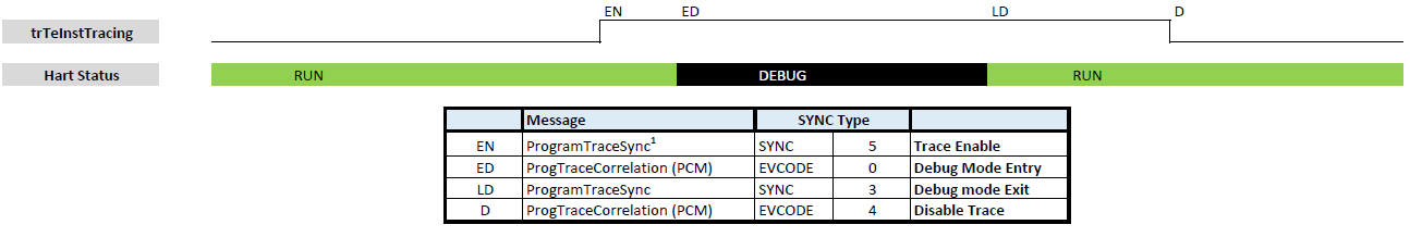
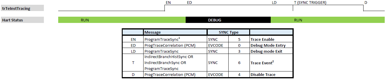
Case1: Enable/disable debug while tracing:
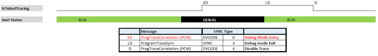
Case2: Enable trace while in debug:
Case3: Disable trace while in debug:
Case4: Sync trigger event (internal or external):
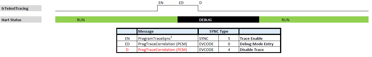
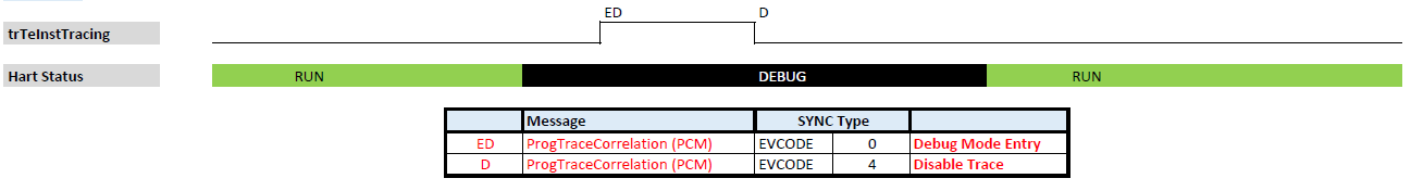
Case5: Enable and disable while in debug:
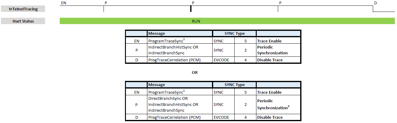
Case6: Periodic synchronization:
-
First possibility provides choice of messages generated at exact periodic synchronization event
P. -
Second provides a choice of messages which may be generated delayed after the periodic event
P.
Superscript notes:
-
ProgramTraceSync message may be replaced with DirectBranchSync, IndirectBranchHistSync, IndirectBranchHistSync.
-
ProgramTraceSync message may be generated for a SYNC event, however, HIST information will not be reported. For HTM mode, the IndirectBranchHistSync or IndirectBranchSync message with SYNC=6 (Trace Event) should be used to ensure no trace data is lost.
-
Next available …Branch… message upgraded to …Branch…Sync counterpart, so SYNC code is reported.
8.1.5. Timestamp Reporting
Timestamp reporting must be enabled by trTsEnable trace control bit.
If timestamp is enabled, all Synchronizing Messages include an absolute timestamp value with upper zeroes suppressed. Other message types with timestamp emit the timestamp as relative offset from last reported (absolute or relative) timestamp.
| The TSTAMP field is a variable-length field, and most significant bits set to 0 will not be transmitted. This approach provides good compression for both relative and absolute timestamps. |
To reconstruct the full timestamp, software begins at a synchronizing message and stores the TSTAMP value found there, zero-extended to the full timestamp width. Shortly after starting a trace session, even a 64-bit timestamp will typically require far less than 64 bits to transmit. Software extracts the compressed TSTAMP from each message thereafter and adds it with the previous decompressed timestamp to obtain the full timestamp value associated with this message.
The following rules must be observed:
-
If timestamps are enabled, ALL Synchronizing Messages must include an absolute TSTAMP value.
-
It is not required for all non-synchronizing messages to always report a timestamp. Doing so may be opted for saving trace bandwidth or in the case of sending back-to-back messages.
-
The absolute timestamp cannot exceed 64 bits (even with 1ps resolution, 64-bit counters will overflow in about 584 years).
-
Implementations may choose a smaller counter. Trace tools may assume timestamp will not overflow in a single session, although adding support for overflow is not significantly challenging.
-
-
It is suggested that in multi-hart systems, all Trace Encoders use a shared timestamp (for better trace correlation), but it is not mandatory.
-
In all cases, when an address is provided, the timestamp should reflect the time when an event leading to that address occurred.
|
If the above is not feasible, timestamps should be at least reported consistently, ensuring that the time distance between distant events (for example, a periodic timer interrupt) can be reliably calculated. It is necessary to assure that the time reported at exceptions/interrupt handlers reflects the moment when exception or interrupt was observed. |
8.1.6. Corner Cases and Sequences
Normal program flow generates a sequence of messages with I-CNT>0 (reporting at least 1 instruction retired), some HIST fields (to report direct conditional branches) and F-ADDR/U-ADDR fields (to report uninferable unconditional flow changes).
However, sometimes normal flow is interrupted (by exception or interrupt) or some other extra event (trigger/enable/disable) happens and sequence of messages or values of some fields may be a bit unusual. Table below is trying to explain some corner cases.
| Sequence of events | Messages Generated |
|---|---|
Back to back return |
Second message should have I-CNT=1 or 2 (depending on the size of the second return instruction). |
Other back to back jumps or branches |
Same as above (depending on the size of a second instruction). |
Back to back exceptions |
Second message with B-TYPE=2 or 1 (Exception) and I-CNT=0 (nothing executed in between). |
Exception at interrupt destination |
Same as above. |
Pending interrupt at debug mode exit |
ProgTraceSync with SYNC=3 followed by message with B-TYPE=3 or 1 (Interrupt). |
Exception at first instruction traced |
ProgTraceSync with SYNC=3 followed by a message with B-TYPE=2 or 1 (Exception). |
Trace starts disabled |
ProgTraceCorrelation with EVCODE=4 (Trace Disabled). Once trace is enabled message with SYNC=5 (Trace Enable). |
Hart halted with trace disabled |
ProgTraceCorrelation with EVCODE=0 (Enter Debug mode) and I-CNT=0 (nothing executed). |
Exception/Interrupt immediately following trap return |
Usual messages describing instructions up to return from trap (MRET/SRET) instruction. |